Technical details
Leak monitoring system
s
Positive pressure leak detector type DLR-G ...
Single-line system – horizontal and vertical layin
g
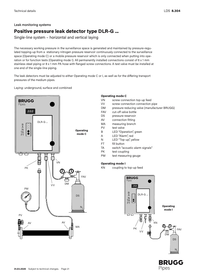
The necessary working pressure in the surveillance space is generated and maintained by pressure-regu-
lated topping-up from a stationary nitrogen pressure reservoir continuously connected to the surveillance
space (Operating mode C) or a mobile pressure reservoir which is only connected when putting into ope
-
ration or for function tests (Operating mode I). All permanently installed connections consist of 6 x 1 m
m
stainless steel piping or 8 x 1 mm PA hose with
flanged screw connections. A test valve must be installed at
one end of the single-line piping
.
The leak detectors must be adjusted to either Operating mode C or I, as well as for the differing transport
pressures of the medium pipes.
Laying: underground, surface and combined
LD
S
8.304
DLR-G ...
B
A
N
T
A
FT
Operating
mode C
V
N
P
K
PM
DM
VV
FAV
N2
Operating mode C
VN
screw connection top-up feed
VV
screw connection connection pipe
DM
pressure reducing valve (manufacturer BRUGG)
FAV
cut-off valve bottle
DS
pressure reservoir
AV
connection fitting
MA
measuring branch
PV
test valve
B
LED “Operation”, green
A
LED “Alarm”, red
N
LED “Top-up”, yellow
FT
fill button
TA
switch “acoustic alarm signals”
PK
test coupling
PM
test measuring gauge
Operating mode I
KN
coupling to top-up feed
DLR-G ..
.
P
V
AV
A
V
DS
M
A
B
A
N
TA
F
T
KN
PK
VV
Operating
mode I
D
M
FAV
D
S
N2
31.03.2026 Subject to technical changes. Page 21

