Technical details
LD
S
8.302
Leak monitoring system
s
Positive pressure leak detector type DLR-G ...
Overview, technical data, constructio
n
Application
Leak detector type DLR-G ... P
M
Operating mode C – continuousl
y
Leak detector type DLR-G ... P
M
Operating mode I – interval
l
Area of us
e
water-hazardous
fluids
underground and surface-laid double-walled pipin
g
water-hazardous
fluid
s
underground double-walled pipin
g
Monitorable
pipe lengt
h
single monitorable pipe length see worksheet LDS 8.13
0
or sum of all pipe lengths L max. = 2000
m
single monitorable pipe length see workshee
t
LDS 8.130 or sum of all pipe lengths L max. = 2000
m
Electric connectio
n
leak detector: 230 V, 50 Hz A
C
distributor block 1,
2
potential-free relay contacts “Alarm
”
230 V, 2 A – distributor block 11, 1
2
leak detector: 230 V, 50 Hz A
C
distributor block 1,
2
potential-free relay contacts “Alarm
”
230 V, 2 A – distributor block 11, 1
2
Leak detectio
n
nitroge
n
nitroge
n
Installation are
a
Install inside a closed, dry room with no access fo
r
unauthorized personnel or outside buildings.
Installation in explosion-proof areas is not permitted
.
Install inside a closed, dry room with no access fo
r
unauthorized personnel or outside buildings
.
Installation in explosion-proof areas is not permitted
.
Generation o
f
extra pressur
e
Pressure reservoir (bottle) with pressure reduction
Nitrogen bottle with pressure reduction valve fo
r
operation or function test, mobil
e
Extra function
s
via potential-free rela
y
via potential-free rela
y
Additional criteria
LAZ technically adapted to operating pressure of
doublewalled piping
LAZ technically adapted to operating pressure o
f
doublewalled piping
Housing dimensions
height
width
depth
280 mm 230 mm 130 m
m
height
width
depth
280 mm 230 mm 130 m
m
Fitting
s
distributor block type HMB, 2 – 8 connections to
double-walled pipin
g
Insulator type ET to separate the metal connection
in earthed installations acc. to TRbF 52
1
distributor block type HMB, 2 – 8 connections to
double-walled pipin
g
Insulator type ET to separate the metal connection
in earthed installations acc. to TRbF 52
1
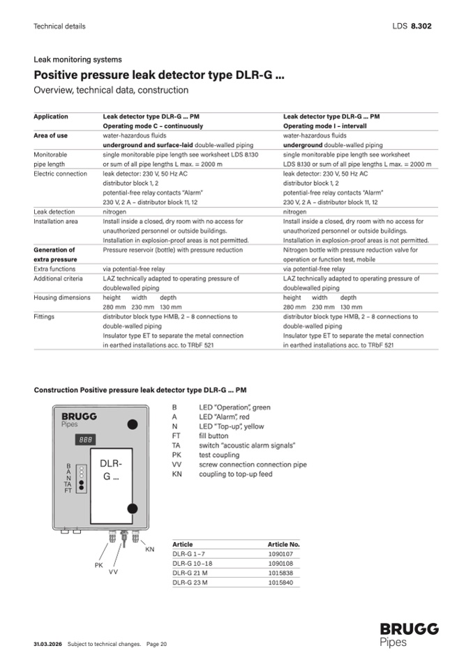
Construction Positive pressure leak detector type DLR-G ... P
M
B
A
N
T
A
FT
DLR
-
G ...
B
LED “Operation”, gree
n
A
LED “Alarm”, red
N
LED “Top-up”, yello
w
FT
fill butto
n
TA
switch “acoustic alarm signals
”
PK
test coupling
VV
screw connection connection pip
e
KN
coupling to top-up feed
Article
Article No
.
KN
DLR-G 1–7
1090107
P
K
DLR-G 10 –18
1090108
VV
DLR-G 21 M
1015838
DLR-G 23 M
1015840
31.03.2026 Subject to technical changes. Page 20

