Technical details
LD
S
8.305
Leak monitoring system
s
Positive pressure leak detector type DLR-G ... PM
Two- and multiple line system – horizontal and vertical laying
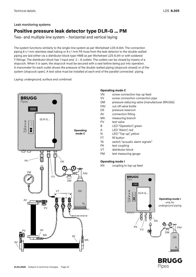
The system functions similarly to the single-line system as per Worksheet LDS 8.304. The connectio
n
piping 6 x 1 mm stainless steel tubing or 8 x 1 mm PA hose from the leak detector to the double-walle
d
piping are laid either via a distributor block type HMB as per Worksheet LDS 8.341 or with soldere
d
T-fittings. The distributor block has 1 input and 2 – 8 outlets. The outlets can be closed by means of a
stopcock. When it is open, the stopcock must be secured with a seal before being put into operation
.
A manometer for each outlet shows the pressure of the double-walled piping (stopcock closed) or of the
system (stopcock open). A test valve must be installed at each end of the parallel connected piping
.
Laying: underground, surface and combined
DLR-G ..
.
B
A
N
TA
F
T
PK
V
N
PM
VV
V
T
Operating
mode C
FA
V
DM
D
S
Operating mode
C
VN
screw connection top-up fee
d
VV
screw connection connection pip
e
DM
pressure reducing valve (manufacturer BRUGG)
FAV
cut-o
ff valve bottl
e
DS
pressure reservoir
AV
connection
fitting
MA
measuring branc
h
PV
test valv
e
B
LED “Operation”, gree
n
A
LED “Alarm”, re
d
N
LED “Top-up”, yello
w
FT
fill butto
n
TA
switch “acoustic alarm signals
”
PK
test couplin
g
VT
distributor bloc
k
PM
test measuring gaug
e
Operating mode
I
KN
coupling to top-up fee
d
B
A
N
TA
F
T
DLR-G ..
.
A
V
N
2
Operating mode
I
only fo
r
underground pipin
g
P
V
KN
PK
FAV
AV
VV
PV
DM
M
A
A
V
DS
MA
A
V
N
2
31.03.2026 Subject to technical changes. Page 22

