Technical details
LD
S
8.301
Leak monitoring system
s
Positive pressure leak detector type DLR-G ... PM
Switching pressure
s
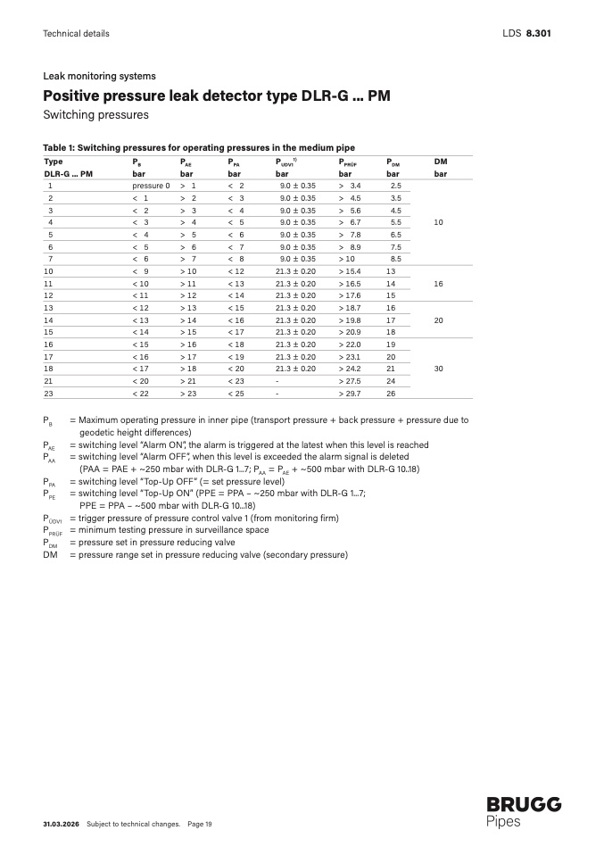
Table 1: Switching pressures for operating pressures in the medium pipe
Type
PB
PAE
PPA
PUDV1
1
)
PPRÜF
PDM
D
M
DLR-G ... PM
bar
bar
bar
bar
bar
bar
ba
r
1
pressure 0 > 1
< 2
9.0 ± 0.35
> 3.4
2.5
2
< 1
> 2
< 3
9.0 ± 0.35
> 4.5
3.5
3
< 2
> 3
< 4
9.0 ± 0.35
> 5.6
4.5
4
< 3
> 4
< 5
9.0 ± 0.35
> 6.7
5.5
1
0
5
< 4
> 5
< 6
9.0 ± 0.35
> 7.8
6.5
6
< 5
> 6
< 7
9.0 ± 0.35
> 8.9
7.5
7
< 6
> 7
< 8
9.0 ± 0.35
> 10
8.5
10
< 9
> 10
< 12
21.3 ± 0.20
> 15.4
1
3
11
< 10
> 11
< 13
21.3 ± 0.20
> 16.5
14
1
6
12
< 11
> 12
< 14
21.3 ± 0.20
> 17.6
1
5
13
< 12
> 13
< 15
21.3 ± 0.20
> 18.7
1
6
14
< 13
> 14
< 16
21.3 ± 0.20
> 19.8
17
2
0
15
< 14
> 15
< 17
21.3 ± 0.20
> 20.9
1
8
16
< 15
> 16
< 18
21.3 ± 0.20
> 22.0
1
9
17
< 16
> 17
< 19
21.3 ± 0.20
> 23.1
2
0
18
< 17
> 18
< 20
21.3 ± 0.20
> 24.2
21
3
0
21
< 20
> 21
< 2
3
-
> 27.5
2
4
23
< 22
> 23
< 2
5
-
> 29.7
2
6
PB
= Maximum operating pressure in inner pipe (transport pressure + back pressure + pressure due t
o
geodetic height di
fferences)
PAE
PAA
= switching level “Alarm ON”, the alarm is triggered at the latest when this level is reached
= switching level “Alarm OFF”, when this level is exceeded the alarm signal is deleted
(PAA = PAE + ~250 mbar with DLR-G 1...7; PAA = PAE + ~500 mbar with DLR-G 10..18)
PPA
PPE
= switching level “Top-Up OFF” (= set pressure level)
= switching level “Top-Up ON” (PPE = PPA – ~250 mbar with DLR-G 1...7
;
PPE = PPA – ~500 mbar with DLR-G 10...18)
PÜDV1
PPRÜF
PDM
= trigger pressure of pressure control valve 1 (from monitoring firm)
= minimum testing pressure in surveillance spac
e
= pressure set in pressure reducing valv
e
DM = pressure range set in pressure reducing valve (secondary pressure
)
31.03.2026 Subject to technical changes. Page 19

