BG
T
Installation instructions
1.701
BIOFLEX Pipe system
Installation instructions Fermenter
Installing the pipe work CNW 60/66, DN 50 with connector and seal
7 The corrugated pipe is led out of the tank wit
h
the bending support (as described on Datasheet
BGT 1.800
)
The BIOFLEX connector lies outside the tank. The wel-
ded-on wall duct lies inside the tank wall. For installatio
n
instructions for the leading out of the BIOFLEX pipe with
its connector and gasket insert, see Figs. 10 to 47
.
9 Fitting the double nipple (pipe
fitting) with flange plate
Version for steel tanks or concrete tanks (also prefabricated)
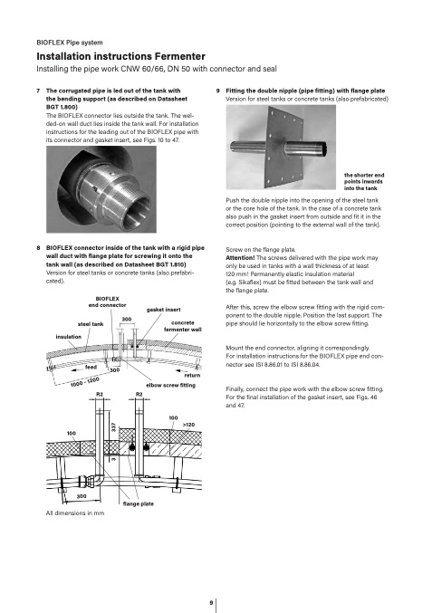
8 BIOFLEX connector inside of the tank with a rigid pip
e
wall duct with
flange plate for screwing it onto the
tank wall (as described on Datasheet BGT 1.810
)
Version for steel tanks or concrete tanks (also prefabri-
cated).
BIOFLE
X
end connector
gasket inser
t
30
0
steel tank
concret
e
fermenter wall
insulatio
n
fee
d
10
00
-
1
20
0
R2
100
3
3
3
7
30
0
R
2
retur
n
elbow screw fitting
100
>12
0
the shorter en
d
points inwards
into the tank
Push the double nipple into the opening of the steel tank
or the core hole of the tank. In the case of a concrete tan
k
also push in the gasket insert from outside and fit it in the
correct position (pointing to the external wall of the tank)
.
Screw on the
flange plate
.
Attention! The screws delivered with the pipe work ma
y
only be used in tanks with a wall thickness of at least
120 mm! Permanently elastic insulation materia
l
(e.g. Sika
flex) must be fitted between the tank wall an
d
the
flange plate
.
After this, screw the elbow screw
fitting with the rigid com
-
ponent to the double nipple. Position the last support. The
pipe should lie horizontally to the elbow screw fitting.
Mount the end connector, aligning it correspondingly
.
For installation instructions for the BIOFLEX pipe end con-
nector see ISI 8.86.01 to ISI 8.86.04
.
Finally, connect the pipe work with the elbow screw
fitting.
For the
final installation of the gasket insert, see Figs. 4
6
and 47
.
30
0
All dimensions in mm
flange plate
24.02.2021 Subject to change without notice. T +49 5031 170-0 · brugg.de Page 2
9

