BGT
Installation instructions
1.70
6
BIOFLEX Pipe system
Installation instructions Fermenter
End connector with graphite sealing ring for corrugated pipe DN 50
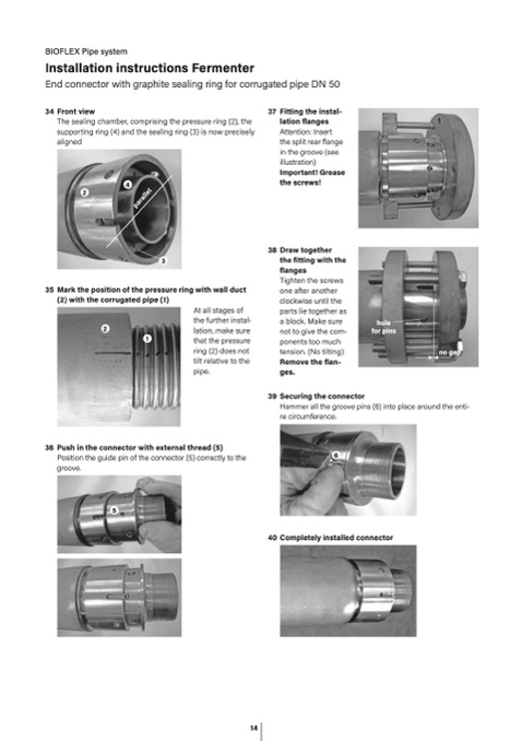
34 Front view
The sealing chamber, comprising the pressure ring (2), th
e
supporting ring (4) and the sealing ring (3) is now precisely
aligned
4
37 Fitting the instal
-
lation flanges
Attention: Inser
t
the split rear flange
in the groove (see
illustration)
Important! Grease
the screws
!
2
p
a
r
a
l
l
e
l
3
35 Mark the position of the pressure ring with wall duct
(2) with the corrugated pipe (1
)
2
1
At all stages of
the further instal-
lation, make sure
that the pressure
ring (2) does not
tilt relative to the
pipe.
38 Draw togethe
r
the fitting with th
e
flange
s
Tighten the screws
one after another
clockwise until th
e
parts lie together as
a block. Make sure
not to give the com
-
ponents too muc
h
tension. (No tilting
)
Remove the flan
-
ges
.
hol
e
for pins
39 Securing the connector
Hammer all the groove pins (6) into place around the enti-
re circumference.
6
no gap
36 Push in the connector with external thread (5)
Position the guide pin of the connector (5) correctly to the
groove.
5
40 Completely installed connector
24.02.2021 Subject to change without notice. T +49 5031 170-0 · brugg.de Page 7
14

