Technical details
Leak monitoring system
s
Vacuum leak detector type VLR 410 PMMV Si
Laying in one line up to max. 25 bar with additional measuring unit ZD 41
0
If the maximum monitorable length acc. to Worksheet LDS 8.120 is not su
fficient for
an individual case the additional measuring unit ZD 410 must be installed
.
Connecting the leak detector to the surveillance space
of the double-walled safety pipe (Worksheet LDS 8.213
)
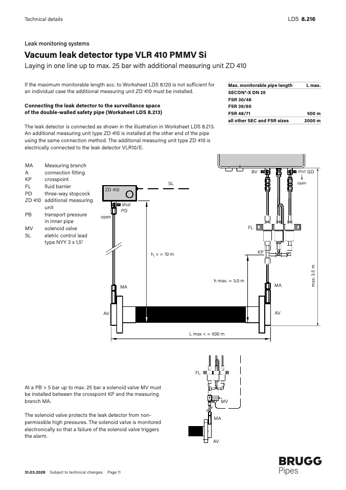
The leak detector is connected as shown in the illustration in Worksheet LDS 8.213.
An additional measuring unit type ZD 410 is installed at the other end of the pip
e
using the same connection method. The additional measuring unit type ZD 410 is
electrically connected to the leak detector VLR10/E.
MA
Measuring branch
A
connection fittin
g
KP
crosspoint
FL
fluid barrier
PD
three-way stopcoc
k
ZD 410 additional measurin
g
uni
t
PB
transport pressure
in inner pipe
MV
solenoid valv
e
SL
eletric control lea
d
type NYY 3 x 1,52
S
L
ZD 41
0
shu
t
P
D
ope
n
LD
S
8.216
Max. monitorable pipe length
L max
.
SECON®-X DN 2
5
FSR 30/4
8
FSR 39/6
0
FSR 48/71
500 m
all other SEC and FSR sizes
2000 m
shut
BV
GD
open
F
L
KP
h1 < = 10 m
h max. = 3.0 m
m
a
x
.
3
.
5
m
M
A
AV
MA
AV
L max < = 500 m
FL
At a PB > 5 bar up to max. 25 bar a solenoid valve MV must
be installed between the crosspoint KP and the measurin
g
branch MA.
The solenoid valve protects the leak detector from non-
permissible high pressures. The solenoid valve is monitore
d
electronically so that a failure of the solenoid valve triggers
the alarm.
M
V
MA
A
V
31.03.2026 Subject to technical changes. Page 11

