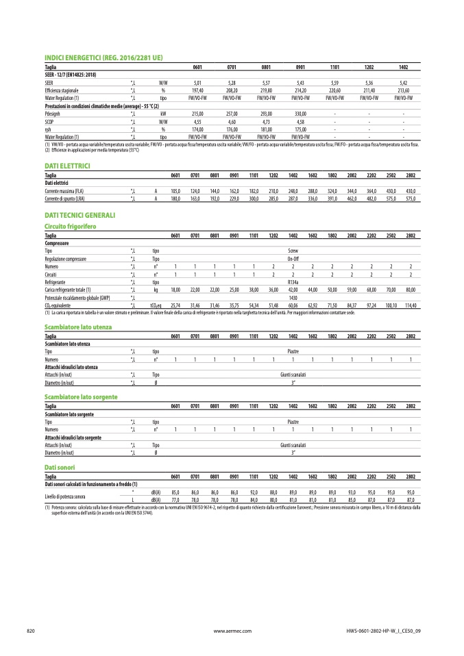
INDICI ENERGETICI (REG. 2016/2281 UE)
Taglia
0601
0701
0801
0901
1101
1202
140
2
SEER - 12/7 (EN14825: 2018)
SEER
°,L
W/W
5,01
5,28
5,57
5,43
5,59
5,36
5,42
Efficienza stagionale
°,L
%
197,40
208,20
219,80
214,20
220,60
211,40
213,60
Water Regulation (1)
°,L
tipo
FW/VO-FW
FW/VO-FW
FW/VO-FW
FW/VO-FW
FW/VO-FW
FW/VO-FW
FW/VO-FW
Prestazioni in condizioni climatiche medie (average) - 55 °C (2
)
Pdesignh
°,L
kW
215,00
257,00
293,00
330,00
-
-
-
SCOP
°,L
W/W
4,55
4,60
4,73
4,58
-
-
-
ηsh
°,L
%
174,00
176,00
181,00
175,00
-
-
-
Water Regulation (1)
°,L
tipo
FW/VO-FW
FW/VO-FW
FW/VO-FW
FW/VO-FW
-
-
-
(1)
VW/VO - portata acqua variabile/temperatura uscita variabile; FW/VO - portata acqua
fissa/temperatura uscita variabile; VW/FO - portata acqua variabile/temperatura uscita fissa; FW/FO - portata acqua fissa/temperatura uscita fissa
.
(2)
Efficienze in applicazioni per media temperatura (55°C)
DATI ELETTRICI
Taglia
Dati elettrici
Corrente massima (FLA)
Corrente di spunto (LRA)
0601
0701
0801
0901
1101
1202
1402
1602
1802
2002
2202
2502
280
2
°,L
A
105,0
124,0
144,0
162,0
182,0
210,0
248,0
288,0
324,0
344,0
364,0
430,0
430,
0
°,L
A
180,0
163,0
192,0
229,0
300,0
285,0
287,0
336,0
391,0
462,0
482,0
575,0
575,
0
DATI TECNICI GENERALI
Circuito frigorifer
o
Taglia
0601
0701
0801
0901
1101
1202
1402
1602
1802
2002
2202
2502
280
2
Compressor
e
Tipo
°,L
tipo
Scre
w
Regolazione compressore
°,L
Tipo
On-O
ff
Numero
°,L
n°
1
1
1
1
1
2
2
2
2
2
2
2
2
Circuiti
°,L
n°
1
1
1
1
1
2
2
2
2
2
2
2
2
Refrigerante
°,L
tipo
R134
a
Carica refrigerante totale (1)
°,L
kg
18,00
22,00
22,00
25,00
38,00
36,00
42,00
44,00
50,00
59,00
68,00
70,00
80,00
Potenziale riscaldamento globale (GWP)
°,L
143
0
CO2 equivalente
°,L
tCO2eq
25,74
31,46
31,46
35,75
54,34
51,48
60,06
62,92
71,50
84,37
97,24
100,10
114,4
0
(1)
La carica riportata in tabella è un valore stimato e preliminare. Il valore
finale della carica di refrigerante è riportato nella targhetta tecnica dell’unità. Per maggiori informazioni contattare sede
.
Scambiatore lato utenz
a
Taglia
0601
0701
0801
0901
1101
1202
1402
1602
1802
2002
2202
2502
280
2
Scambiatore lato utenz
a
Tipo
°,L
tipo
Piastr
e
°,L
n°
1
1
1
1
1
1
1
1
1
1
1
1
1
Numero
Attacchi idraulici lato utenza
Attacchi (in/out)
°,L
Tipo
Giunti scanalat
i
Diametro (in/out)
°,L
Ø
3”
Scambiatore lato sorgente
Taglia
0601
0701
0801
0901
1101
1202
1402
1602
1802
2002
2202
2502
280
2
Scambiatore lato sorgent
e
Tipo
°,L
tipo
Piastr
e
°,L
n°
1
1
1
1
1
1
1
1
1
1
1
1
1
Numero
Attacchi idraulici lato sorgent
e
Attacchi (in/out)
°,L
Tipo
Giunti scanalat
i
Diametro (in/out)
°,L
Ø
3”
Dati sonor
i
Taglia
Dati sonori calcolati in funzionamento a freddo (1
)
Livello di potenza sonora
0601
0701
0801
0901
1101
1202
1402
1602
1802
2002
2202
2502
280
2
(1)
°
dB(A) 85,0
86,0
86,0
86,0
92,0
88,0
89,0
89,0
89,0
93,0
95,0
95,0
95,
0
L
dB(A)
77,0
78,0
78,0
78,0
84,0
80,0
81,0
81,0
81,0
85,0
87,0
87,0
87,
0
Potenza sonora: calcolata sulla base di misure effettuate in accordo con la normativa UNI EN ISO 9614-2, nel rispetto di quanto richiesto dalla certificazione Eurovent.; Pressione sonora misurata in campo libero, a 10 m di distanza dall
a
super
ficie esterna dell’unità (in accordo con la UNI EN ISO 3744)
.
820
www.aermec.com
HWS-0601-2802-HP-W_I_CE50_0
9
A
C
Q
U
A
-
A
C
Q
U
A

