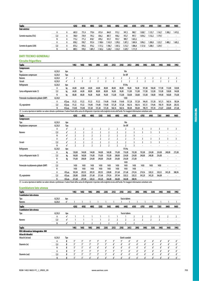
Taglia
Dati elettrici
Corrente massima (FLA)
Corrente di spunto (LRA
)
4202
4502
4802
5202
5602
6002
6402
6503
6703
6903
7203
8403
960
3
A
A
683,9
731,4
770,4
813,4
864,9
913,2
947,2
980,7
1.028,7
1.123,7
1.162,7
1.300,2
1.419,2
E,U
A
700,9
739,9
793,2
836,2
887,7
930,2
972,7
997,7
1.054,2
1.132,2
1.179,7
-
-
N
A
715,2
771,2
818,7
870,2
921,7
955,7
989,7
1.023,2
-
-
-
-
-
A
A
858,2
930,7
953,4
1.108,4
1.163,9
1.290,2
1.287,2
1.069,4
1.096,3
1.200,0
1.222,7
1.480,2
1.603,
2
E,U
A
875,2
939,2
976,2
1.131,2
1.186,7
1.307,2
1.312,7
1.086,4
1.121,8
1.208,5
1.239,7
-
-
N
A
889,5
970,5
1.001,7
1.165,2
1.220,7
1.332,7
1.329,7
1.111,9
-
-
-
-
-
DATI TECNICI GENERALI
Circuito frigorifer
o
Taglia
1402
1602
1802
2002
2202
2352
2502
2652
2802
3002
3202
3402
3602
390
2
Compressor
e
Tipo
A,E,N,U
tipo
Vite
Regolazione compressore
A,E,N,U
Tipo
On-O
ff
Numero
A,E,N,U
n°
2
2
2
2
2
2
2
2
2
2
2
2
2
2
Circuiti
A,E,N,U
n°
2
2
2
2
2
2
2
2
2
2
2
2
2
2
Refrigerante
A,E,N,U
tipo
R134a
A
kg
64,00
64,00
64,00
64,00
80,00
80,00
80,00
96,00
96,00
101,00 106,00 117,00 112,00 128,0
0
Carica refrigerante totale (1)
E,U
kg
64,00
64,00
80,00
80,00
80,00
96,00
96,00
112,00 112,00 117,00 122,00 133,00 128,00 144,00
N
kg
80,00
80,00
96,00
96,00
96,00
112,00 112,00 128,00 128,00 133,00 138,00 149,00 160,00 176,0
0
Potenziale riscaldamento globale (GWP)
A,E,N,U
143
0
A
tCO2eq
91,52
91,52
91,52
91,52
114,40 114,40 114,40 137,28 137,28 144,43 151,58 167,31 160,16 183,04
CO2 equivalent
e
E,U
tCO2eq
91,52
91,52
114,40 114,40 114,40 137,28 137,28 160,16 160,16 167,31 174,46 190,19 183,04 205,9
2
N
tCO2eq 114,40 114,40 137,28 137,28 137,28 160,16 160,16 183,04 183,04 190,19 197,34 213,07 228,80 251,68
(1)
La carica riportata in tabella è un valore stimato e preliminare. Il valore
finale della carica di refrigerante è riportato nella targhetta tecnica dell’unità. Per maggiori informazioni contattare sede
.
Taglia
4202
4502
4802
5202
5602
6002
6402
6503
6703
6903
7203
8403
960
3
Compressor
e
Tipo
A,E,N,U
tipo
Vite
Regolazione compressore
A,E,N,U
Tipo
On-O
ff
A
n°
2
2
2
2
2
2
2
3
3
3
3
3
3
Numer
o
E,U
n°
2
2
2
2
2
2
2
3
3
3
3
-
-
N
n°
2
2
2
2
2
2
2
3
-
-
-
-
-
A
n°
2
2
2
2
2
2
2
3
3
3
3
3
3
Circuit
i
E,U
n°
2
2
2
2
2
2
2
3
3
3
3
-
-
N
n°
2
2
2
2
2
2
2
3
-
-
-
-
-
Refrigerante
A,E,N,U
tipo
R134
a
A
kg
128,00
144,00
144,00
144,00
160,00
176,00
176,00
192,00
192,00
224,00
224,00
240,00
272,00
Carica refrigerante totale (1)
E,U
kg
160,00
160,00
176,00
176,00
192,00
208,00
224,00
224,00
240,00
240,00
256,00
-
-
N
kg
176,00
208,00
224,00
240,00
256,00
256,00
256,00
272,00
-
-
-
-
-
A
143
0
Potenziale riscaldamento globale (GWP
)
E,U
1430
1430
1430
1430
1430
1430
1430
1430
1430
1430
1430
-
-
N
1430
1430
1430
1430
1430
1430
1430
1430
-
-
-
-
-
A
tCO2eq
183,04
205,92
205,92
205,92
228,80
251,68
251,68
274,56
274,56
320,32
320,32
343,20
388,96
CO2 equivalent
e
E,U
tCO2eq
228,80
228,80
251,68
251,68
274,56
297,44
320,32
320,32
343,20
343,20
366,08
-
-
N
tCO2eq
251,68
297,44
320,32
343,20
366,08
366,08
366,08
388,96
-
-
-
-
-
(1)
La carica riportata in tabella è un valore stimato e preliminare. Il valore
finale della carica di refrigerante è riportato nella targhetta tecnica dell’unità. Per maggiori informazioni contattare sede
.
Scambiatore lato utenz
a
Taglia
1402
1602
1802
2002
2202
2352
2502
2652
2802
3002
3202
3402
3602
390
2
Scambiatore lato utenz
a
Tipo
A,E,N,U
tipo
Fascio tubiero
Numero
A,E,N,U
n°
1
1
1
1
1
1
1
1
1
1
1
1
1
1
Taglia
Scambiatore lato utenz
a
4202
4502
4802
5202
5602
6002
6402
6503
6703
6903
7203
8403
960
3
Tipo
A,E,N,U
tipo
Fascio tubiero
A
n°
1
1
1
1
1
1
1
2
2
2
2
2
2
Numer
o
E,U
n°
1
1
1
1
2
2
2
2
2
2
2
-
-
N
n°
1
2
2
2
2
2
2
2
-
-
-
-
-
Taglia
Kit idronico integrato: 00
Attacchi idraulici
1402
1602
1802
2002
2202
2352
2502
2652
2802
3002
3202
3402
3602
390
2
Attacchi (in/out)
A,E,N,U
Tipo
Giunti scanalat
i
A
Ø
5”
5”
5”
5”
5”
5”
5”
6”
6”
6”
6”
6”
6”
6”
Diametro (in
)
E,U
Ø
5”
5”
5”
5”
5”
6”
6”
6”
6”
6”
6”
6”
6”
6
”
N
Ø
5”
5”
6”
6”
6”
6”
6”
6”
6”
6”
6”
6”
6”
6
”
A
Ø
5”
5”
5”
5”
5”
5”
5”
6”
6”
6”
6”
6”
6”
6
”
Diametro (out)
E,U
Ø
5”
5”
5”
5”
5”
6”
6”
6”
6”
6”
6”
6”
6”
6
”
N
Ø
5”
5”
6”
6”
6”
6”
6”
6”
6”
6”
6”
6”
6”
6
”
F
R
E
E
C
O
O
L
I
N
G
NSM-1402-9603-FC_I_UN50_0
9
www.aermec.com
705

